Physical Address
304 North Cardinal St.
Dorchester Center, MA 02124
Physical Address
304 North Cardinal St.
Dorchester Center, MA 02124
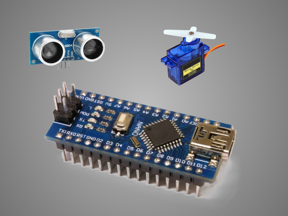
The Arduino Nano is a compact, breadboard-friendly microcontroller board based on the ATmega328P (or sometimes ATmega168). It’s part of the Arduino family and is ideal for small-scale projects where space is limited.
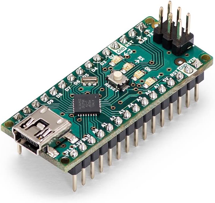
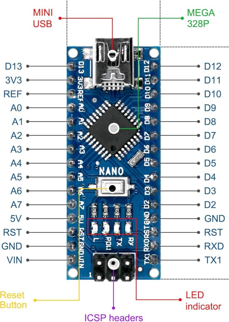
A microcontroller is the central processing unit (CPU) of the Arduino Nano. It’s like the brain that controls everything. It processes the code you upload and interacts with inputs (like sensors) and outputs (like LEDs or motors).
The Arduino Nano’s USB port serves two primary functions: programming the board and providing power via a USB connection. It allows you to upload code from your computer to the Nano and also acts as a 5V power source.
There are 14 digital pins on Arduino Nano from D0 to D13. Digital pins can be configured as either inputs or outputs. These pins offer two voltage levels: HIGH (5V) and LOW (0V). They can be used as inputs to read data from devices like switches and sensors or send digital signals to control buttons, LEDs, relays, and other devices.
Pins D3, D5, D6, D9, D10, and D11 are PWM (Pulse Width Modulation) ports. In addition to digital input/output, PWM Pins can generate Pulse Width Modulated (PWM) signals, which simulate analog output, a continuous signal, by switching ON/OFF a signal rapidly. PWM is often used for dimming LEDs or controlling motor speed and other applications that require a variable voltage level.
RX (D0) and TX (D1) are used for serial communication with a computer or other devices. They transmit and receive data using the UART protocol.
Pins D0 and D1 are digital I/O pins, but they have a primary function as serial communication pins (RX/TX). When used for serial communication, they cannot be used for general digital I/O. If serial communication is not needed, they can be used as regular digital I/O.
There are 8 analog pins from A0 to A7 for reading analog signals. An analog signal is a continuous signal that can take on any value within a specific range.
Show serial communication activity. It is useful for debugging.
Restarts the program running on the board without needing to unplug.
There are a few ways to power the Arduino Nano board.
The most common and convenient way to power an Arduino Nano is through its micro-USB connector. The USB connector provides a regulated 5V line.

Connect 7–12V to the Vin Pin and GND. The onboard regulator steps it down to 5V.
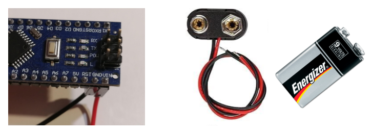
You can power the Arduino Nano from the 3.3V pin or the 5V pin. However, it is not recommended as powering the Nano through these pins bypasses the onboard voltage regulator, which can damage the board.
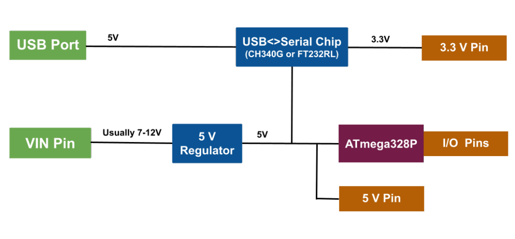
The Arduino Nano does not have a separate 3.3V regulator like the Arduino Uno does. The 3.3V supply on the Nano is derived from the USB-to-serial chip (CH340G or FT232RL).
Visit Getting to Know Your Arduino Uno: A Beginner’s Guide to Its Components for more information.
The Arduino IDE (Integrated Development Environment) is the software application used to write, compile, and upload code to Arduino boards. For more information, visit Getting Started with Arduino IDE: A Beginner’s Guide to Coding and Creating.