Physical Address
304 North Cardinal St.
Dorchester Center, MA 02124
Physical Address
304 North Cardinal St.
Dorchester Center, MA 02124
Arduino Uno is one of the most popular microcontroller boards in the Arduino family. It is widely used for various DIY electronics and prototyping projects. Arduino UNO R3 is the main successor in this series and the most popular official Arduino UNO board. Arduino UNO R4 is an upgraded version of UNO R3, available in two variants: UNO R4 Minima and UNO R4 Wi-Fi.
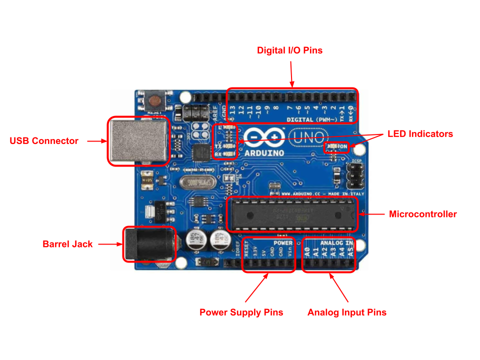
Here’s an overview of the key functional parts of Arduino UNO R3:
The heart of the Arduino Uno, the ATmega328P, is an 8-bit microcontroller that executes the code you upload. It processes inputs from sensors, runs algorithms, and controls outputs to motors, LEDs, and other devices.
This area includes 14 digital input/output pins from 0 to 13. Pins 3, 5, 6, 9, 10, and 11 are PWM (Pulse Width Modulation) ports marked with ~. There is a built-in LED on pin 13, which is often used to test simple programs and troubleshoot.
Digital pins can be configured as either inputs or outputs. These pins offer two voltage levels: HIGH (5V) and LOW (0V). They can be used as inputs to read data from devices like switches and sensors or send digital signals to control buttons, LEDs, relays, and other devices. When set to LOW, a pin outputs 0V to external devices, while setting it to HIGH provides 5V, enabling the triggering of relays or LED illumination.
PWM Pins: In addition to digital input/output, these pins can generate Pulse Width Modulated (PWM) signals, which simulate analog output, a continuous signal, by switching ON/OFF a signal rapidly. PWM is often used for dimming LEDs or controlling motor speed and other applications that require a variable voltage level.
The RX (D0) and TX (D1) pins are used for serial communication. The RX pin receives data, and the TX pin transmits data.
Pins D0 and D1 are digital I/O pins, but they have a primary function as serial communication pins (RX/TX). When used for serial communication, they cannot be used for general digital I/O. If serial communication is not needed, they can be used as regular digital I/O.
This area includes 6 pins from A0 to A5. These pins can be used as both analog and digital inputs. Analog Input pins can read analog signals from sensors, such as temperature sensors, light sensors, and potentiometers in the form of voltage levels between 0V to 5V. These signals are converted into digital values using the ADC (Analog to Digital Converter).
Arduino Uno boards have several ways in which they can be powered:
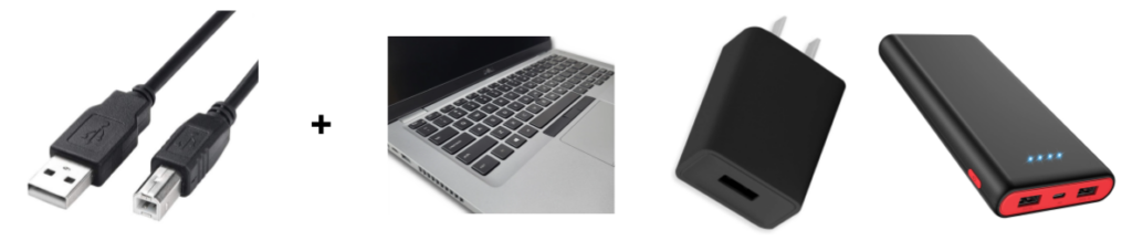
It provides 5V DC voltage and can be sourced from a PC, wall socket adapter, or portable power bank.
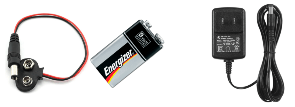
It provides 7-12V for R3 and 6-24V for R4. The current goes through the built-in 5V voltage regulator.
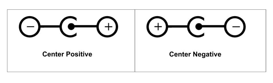
The barrel jack connector is designed to be center-positive for an Arduino Uno. This means the connector’s center pin is the positive (+) terminal, and the outer sleeve is the negative (-) terminal.
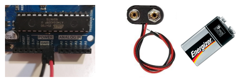
To power an Arduino board using a DC barrel jack, you’ll need a power supply or battery connector with a center positive configuration.
To distinguish a center-positive plug from a center-negative plug, look for a symbol on the plug.
Supply voltage from a regulated power source directly to the Vin pin. Connect the positive wire from the power supply to Vin and the negative to GND. Vin is used to supply the positive voltage from 7-12 V. It is regulated internally by the board to 5V.
The Vin pin does not have reverse polarity protection and connects directly to the voltage regulator. You must be very careful when powering through Vin to avoid damaging the board if you connect the polarity incorrectly.
The Vin pin can also work as a voltage output when an external power supply is connected to the barrel jack connector or USB.
3.3V and 5V pins can be used as power inputs if no regulated power supply is connected through the other power inputs (USB port, barrel jack connector, or VIN pin). However, it is not recommended as it can damage the board’s voltage regulator.
3.3V and 5V pins can work as power outputs since these pins are directly connected to the onboard 3.3V and 5V voltage regulator outputs. They can be supplied with power either from the barrel adapter, the USB connector, or the Vin pin of the board.
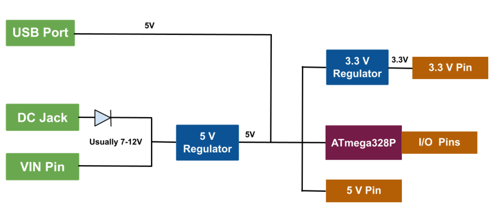
When powering an Arduino Uno through the barrel jack or Vin pin, the current first passes through the built-in 5V voltage regulator. This regulator steps down the input voltage (typically 7-12V) to 5V. Then, another 3.3V voltage regulator steps down the 5V output to 3.3V.
The regulated 5V and 3.3V voltages are then available on the corresponding 5V and 3.3V power pins on the Arduino Uno board. These pins can be used to power external sensors, LEDs, and other low-power components.
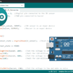
The Arduino IDE (Integrated Development Environment) is the software application used to write, compile, and upload code to Arduino boards. For more information, visit Getting Started with Arduino IDE: A Beginner’s Guide to Coding and Creating.