Physical Address
304 North Cardinal St.
Dorchester Center, MA 02124
Physical Address
304 North Cardinal St.
Dorchester Center, MA 02124

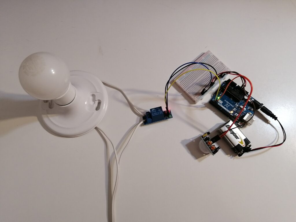
In this article, we’ll walk you through the process of designing and building a simple automated light system using a PIR sensor.
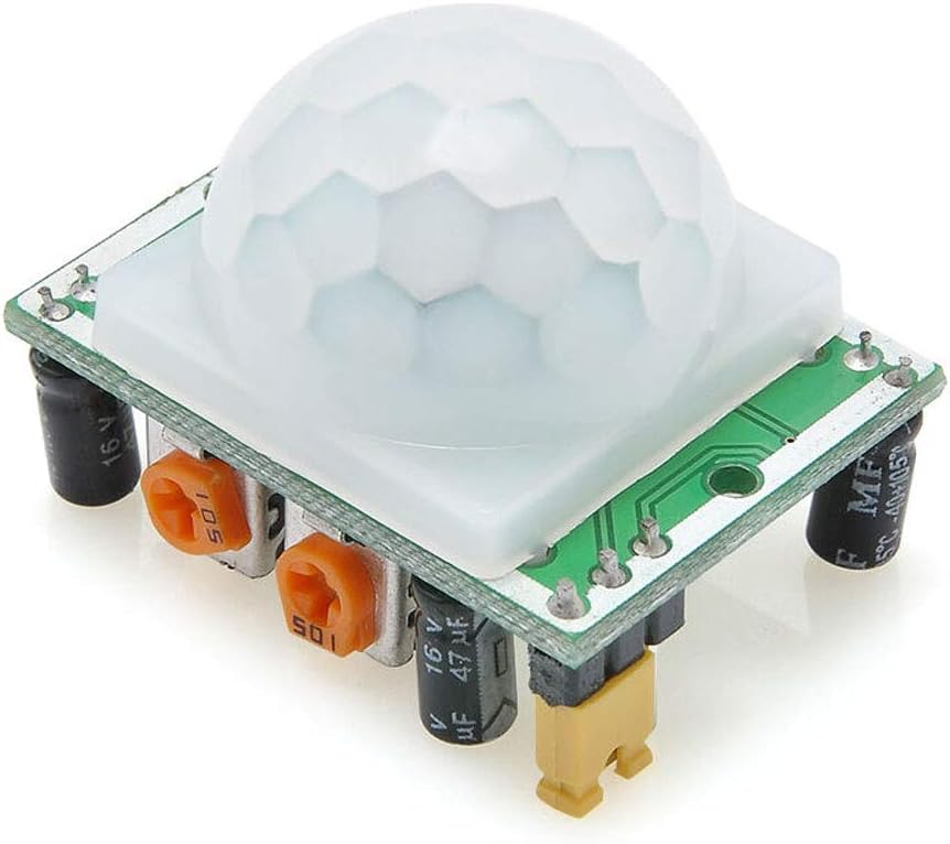
A PIR sensor is a type of sensor used to detect motion by measuring the infrared radiation (heat) emitted by objects. It is commonly used in motion detectors, security systems, and lighting applications.
Visit Introduction to PIR Sensor: What Is It and How Does It Work? for more details about PIR sensors.
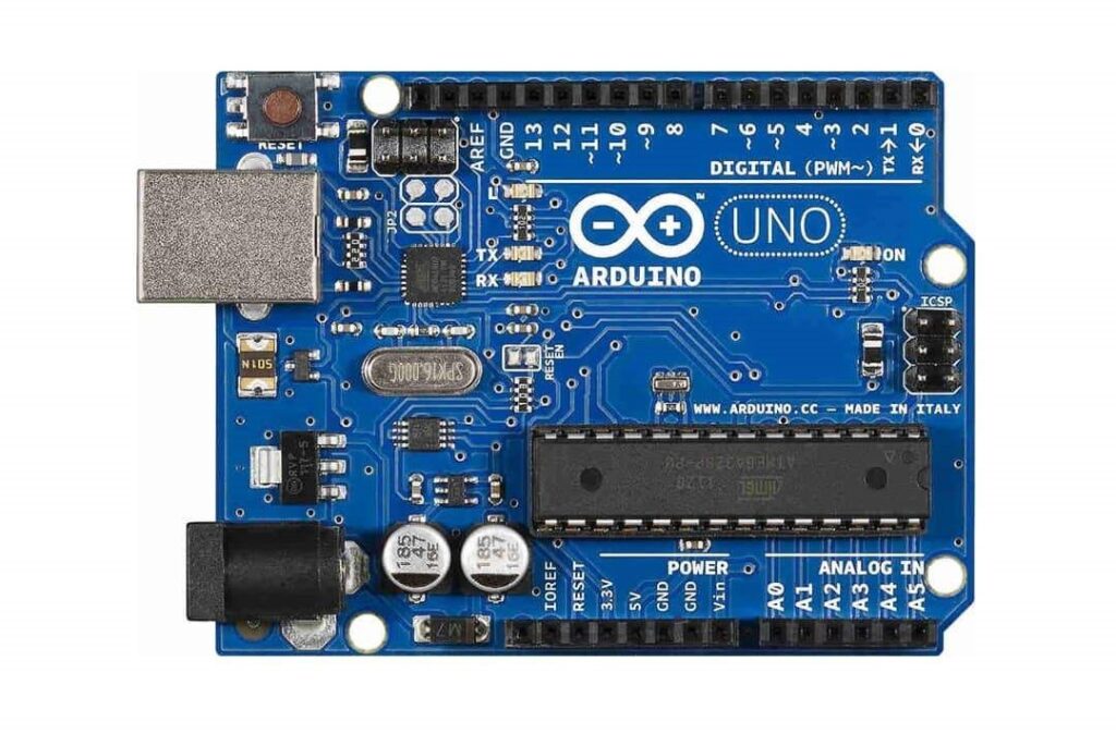
For more information, visit Getting to Know Your Arduino Uno: A Beginner’s Guide to Its Components.


The circuit diagram for this project is provided below, and the details will be discussed in the setup section.
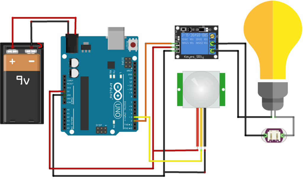
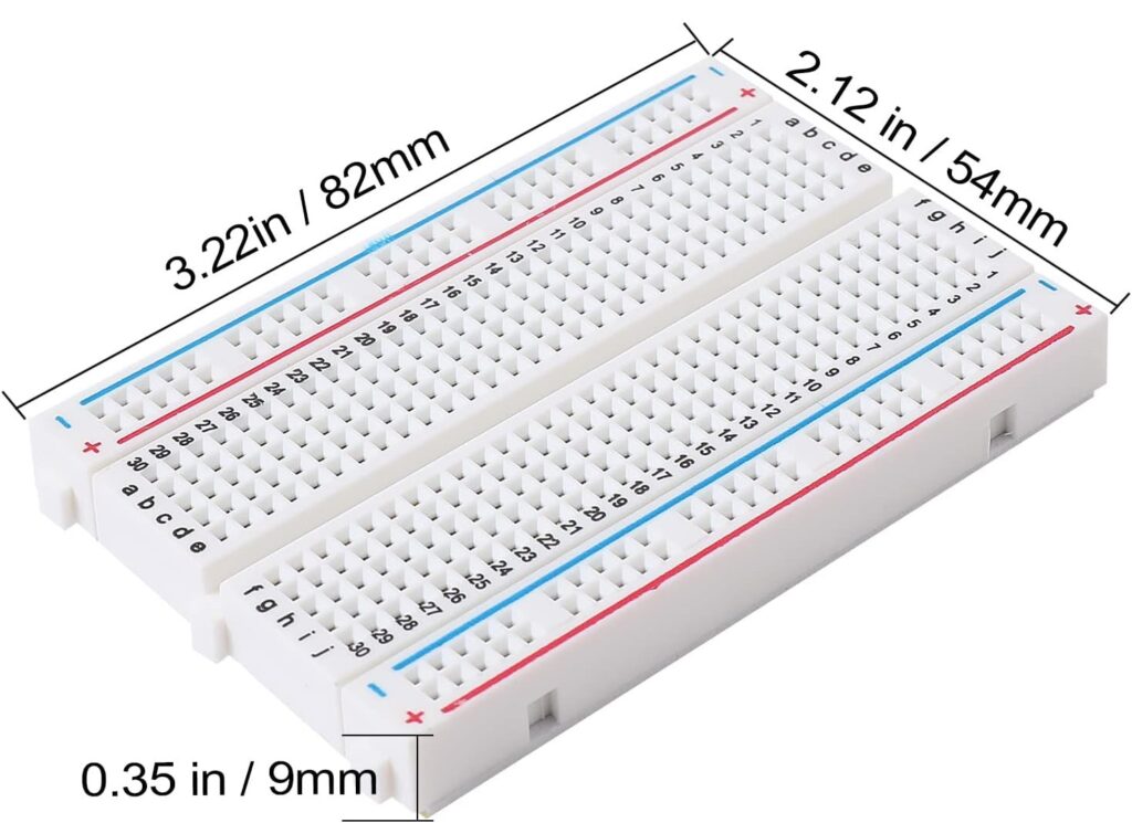
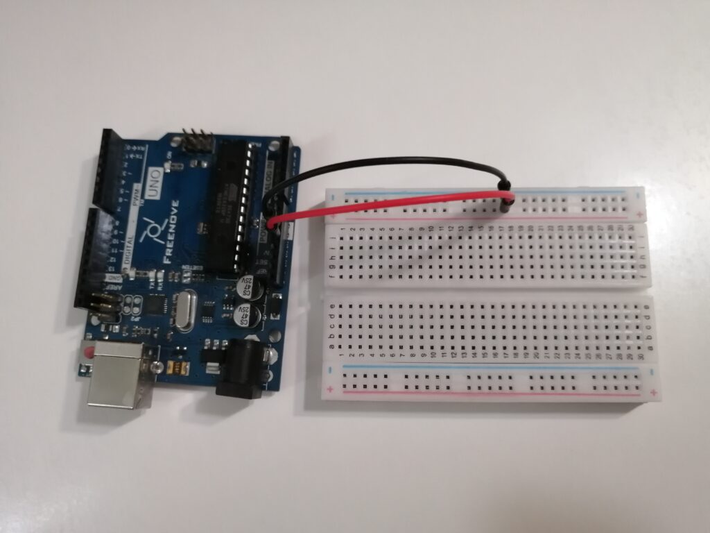
| Arduino | Breadboard |
| 5V | + |
| GND | – |
| PIR Sensor | Arduino | Breadboard |
| GND | – | |
| OUT | D3 | |
| VCC | + |

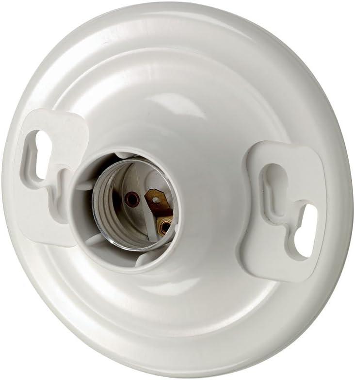
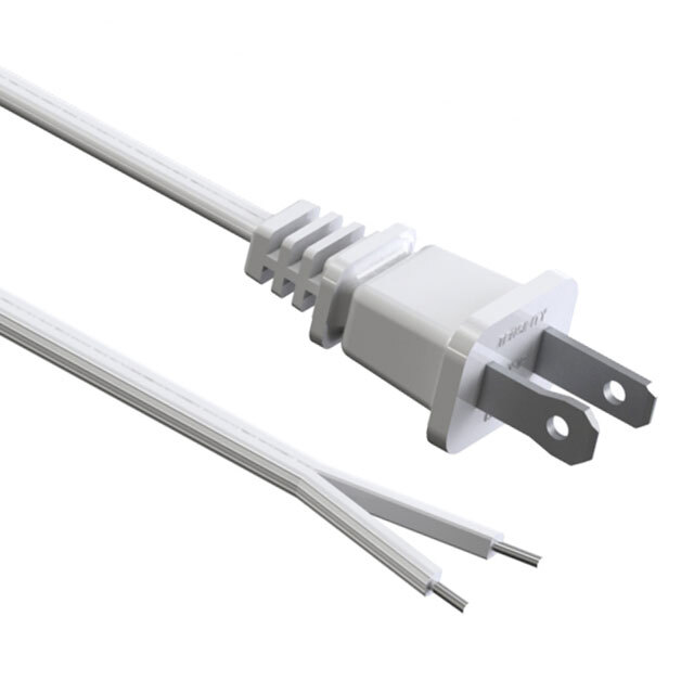
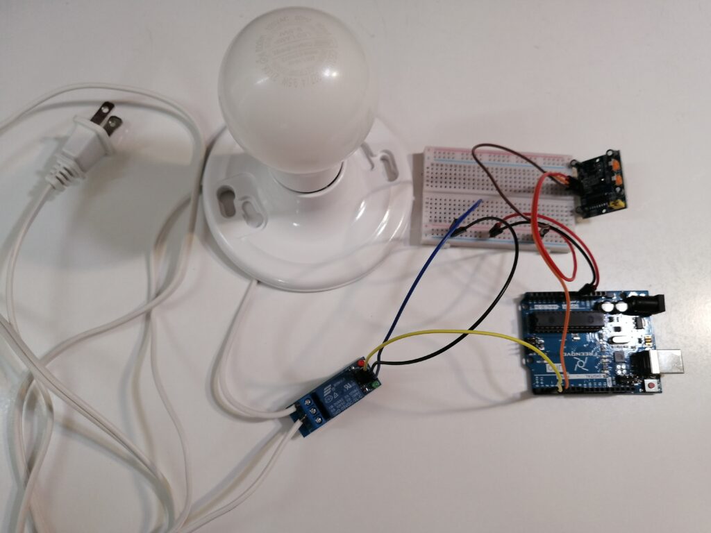
First, distinguish the hot wire and the neutral wire. In polarized plugs, the hot wire, which carries electrical current, is typically the one with the smooth insulation and the narrow blade, while the neutral wire has a ribbed or grooved insulation and a wider blade.
Connect the hot wire to the brass screw terminal and the neutral wire to the silver screw terminal. The details are in the video Which Wire is Hot on a Lamp Cord.


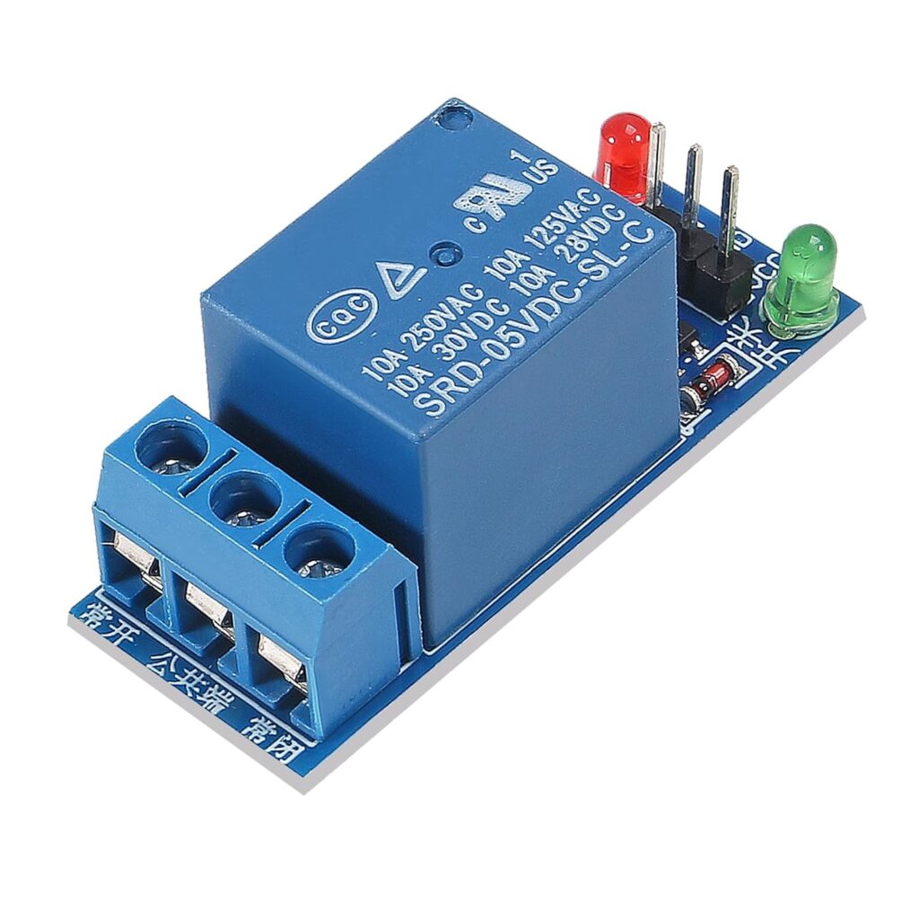
Connect the side leading to the light bulb to the NO terminal of the relay, and the side leading to the plug to the COM terminal.
It’s unsafe to switch the neutral wire with a relay, as it can create a hazardous situation where parts of the circuit remain energized even when the device is “off,” potentially leading to dangerous shocks or equipment damage.

| Relay | Arduino | Breadboard |
| VCC | + | |
| GND | – | |
| IN | D2 |
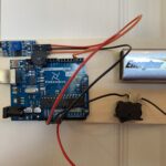
Connect the Arduino to your computer using a USB cable. Upload the program to the Arduino through the Arduino IDE software. Visit Getting Started with Arduino IDE: A Beginner’s Guide to Coding and Creating for more information.


Warning: Disconnect the USB cable or adapter before connecting the battery.
Warning: This project involves high voltages. Incorrect or improper use could result in serious injuries or death. Be extremely careful when connecting the bulb and relay to the mains power supply. Expert supervision is highly recommended.
We use the low level trigger relay and normally open mode in this project. The circuit is normally open. The relay is activated when the control pin receives a low signal (0V). Then, the NO contact closes the circuit, causing the light to turn on.
For further information, visit An Essential Introduction to DC Relays in Arduino Projects: What They Are and How They Work.
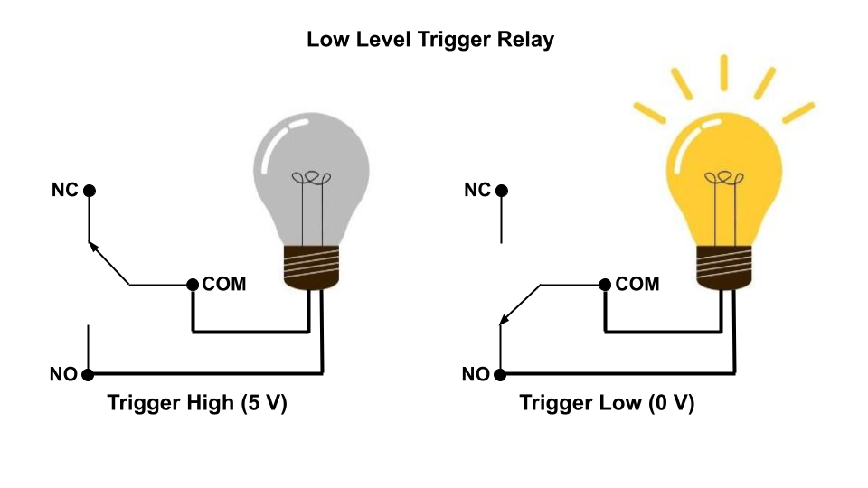
If object movement is detected, the sensor value will be High. Then the Low signal will be sent to the relay. The activated relay will turn on the light.
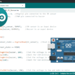
#define SENSOR_PIN 3
#define RELAY_PIN 2

void setup()
{
  pinMode(RELAY_PIN, OUTPUT);
  pinMode(SENSOR_PIN, INPUT);
}

void loop()
{
  //If object movement is detected then the sensor value will be 1 else the value will be 0
  int sensorValue = digitalRead(SENSOR_PIN);

  if (sensorValue == HIGH)
  {
    digitalWrite(RELAY_PIN, LOW);  //Relay is low level trigger relay so we need to write LOW to switch on the light
  }
  else
  {
    digitalWrite(RELAY_PIN, HIGH);
  }
}