Physical Address
304 North Cardinal St.
Dorchester Center, MA 02124
Physical Address
304 North Cardinal St.
Dorchester Center, MA 02124

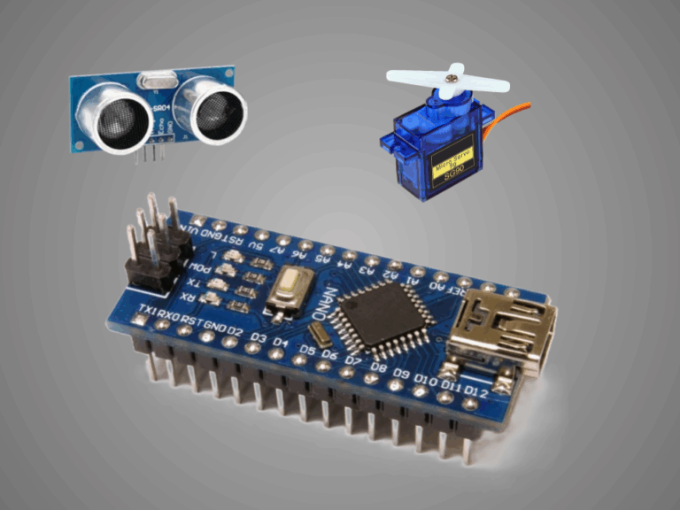
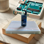
DC relays are essential components in many Arduino projects, allowing you to control high-power devices like motors, lights, or other electrical equipment using the low-power signals from an Arduino board. A relay acts as an electrically operated switch that can be turned on or off, controlling the flow of current. In this article, we’ll explore the basics of relays, how they work, and how you can integrate them into your projects to expand the capabilities of your system.
In an Arduino project, understanding the input and output interfaces of a DC relay is crucial for controlling high-power devices safely and efficiently. Let’s break down these two interfaces:
The input interface refers to the part of the relay that receives the low-power control signal from the Arduino. There are three connection pins in this area.
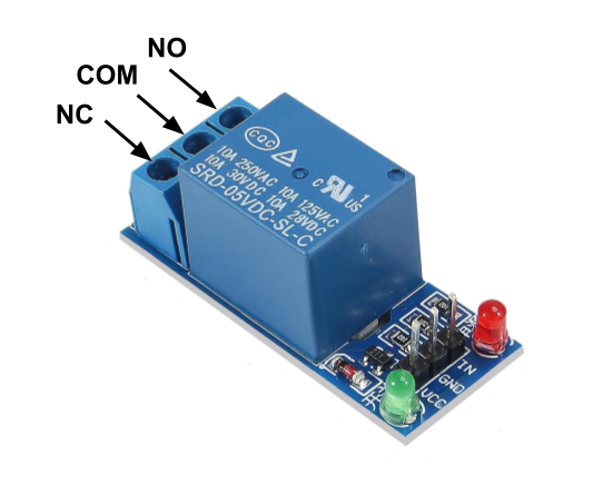
The output interface refers to the part of the relay that controls the external high-power circuit. The relay has a set of switch contacts, usually labeled as NO (Normally Open), NC (Normally Closed), and COM (Common). These contacts connect to an external circuit or device (e.g., a motor, light, or fan) that the relay will control.
We usually only use two of these pins:
In relay-based circuits, the terms “high-level trigger” and “low-level trigger” refer to how the relay is activated, based on the input signal provided to the relay’s control pin. The trigger type determines whether the relay is activated when the input signal is high (5V) or low (0V).
There are two input modes that make the relay works oppositely.
There are two output modes that make the relay works oppositely.
The combination of input and output modes includes:
The next will show the normally open mode in detail.

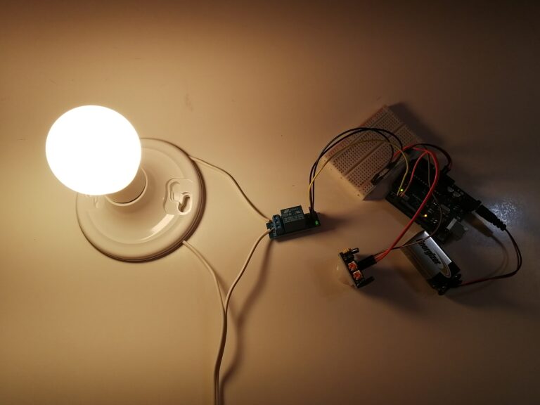
The circuit is normally open. The relay is activated when the control pin receives a low signal (0V). Then, the NO contact closes the circuit, causing the light to turn on.
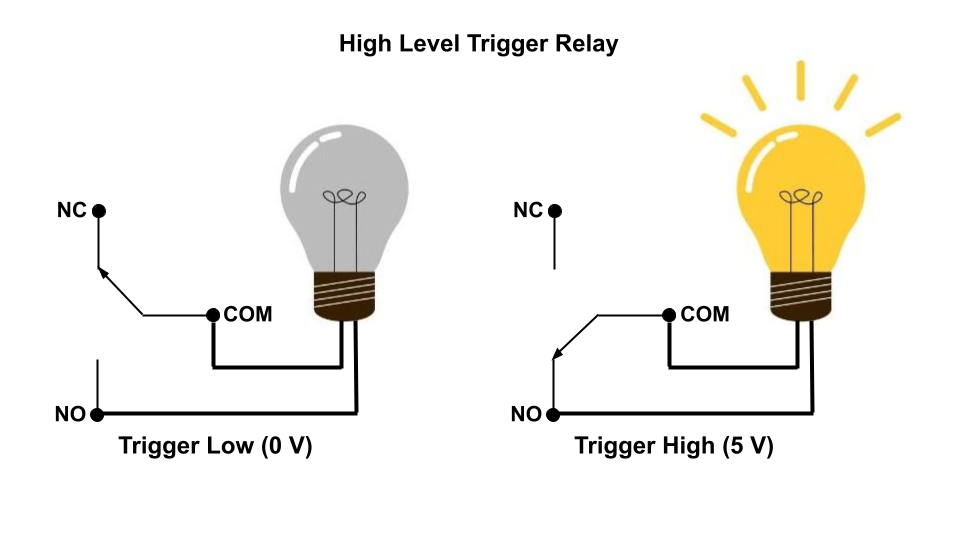
The circuit is normally open. The relay is activated when a high voltage (5V) is applied to its control pin. Then, the the circuit is closed and the lamp lights on.
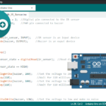
// Low-level trigger relay

#define RELAY_PIN 2

void setup()
{
  pinMode(RELAY_PIN, OUTPUT);
}

// Switch on/off relay after every 2 seconds.
// LOW signal will turn on relay and HIGH signal will turn off relay.

void loop()
{
  digitalWrite(RELAY_PIN, LOW);
  delay(2000);
  digitalWrite(RELAY_PIN, HIGH);
  delay(2000);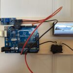
}The following example demonstrates the Arduino project incorporating the DC relay.